KIKA Nuclear Cranes Seminar 2008
– Critical Spots
Three critical spots for safe crane operations
The main aim for all crane users at nuclear facilities is to ensure safe operations of lifting equipment in any conditions. The single-failure-proof concept is a commonly adapted model to achieve low risk levels. At the KIKA Nuclear Cranes Seminar three critical components for maximum safety were identified.
The gearbox
A failure in the gear box is a high-risk incident as it often means uncontrolled drop of load Walter Heinrich and Kjell Andersson from Inspecta Sweden presented a number of cases with different backgrounds.
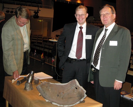
The reasons for breakdowns included too sharp a radius on shaft, misalignment of centreline due to welding of hoisting drum, and the wrong type of couplings. In the latter case the primary shaft of a gear box for an 80-ton bridge crane broke down. A crude rubber coupling element with a hardness of 57 Shore A and a stiffness of 20 kN/mm had been exchanged into a polyurethane element with a hardness of 95 Shore A and a stiffness of 110 kN/mm. The stresses in the critical cross-section regarding certain values of misalignment widely exceeded the permitted limits. This caused a high bending moment on the shaft, which was broken after only 386 hours of use. That should be seen in the light of the 50 000 hours’ life expectancy. Part of the drum brake was found 250 metres away in a neighbouring factory.
Welding repair on gearbox components can also be a security threat. Heat treatment of the material should be followed by magnetic testing at least 48 hours after welding. Otherwise there is a risk of delayed cracks. Many incidents occur when the centreline position has been changed – one should check the alignment or install a coupling to improve flexibility of the shaft line.
The gearbox manufacturers have also implemented new features to further enhance the safety level of this vital component. The housing for gearboxes is made of fabricated steel, which avoids potential deformations of the crane structure. Longitudinal tooth correction is made to anticipate torsional and flexion deformation of the gears and the shafts during operation with full load. The teeth of the gearbox are often carburized and ground and the gearbox is laser aligned before final installation.

The backup brake
The backup brake is covered by EN and prEN standards, which however do not cover hazards resulting from handling radiating material. According to prEN 15011 the backup brake shall be initiated immediately when a failure has been detected in the service braking system or in the kinematic chain.
A crane operator can cause a dangerous situation by resetting the emergency stop, which may lead to drop of the cargo if the emergency stop has been initiated by a system failure. A Swedish study of 14 references performed in 2003 showed that unintentional engagement of the backup brake was quite common. Unintentional engagement of the backup brake creates huge forces into the load-bearing chain, which is not calculated in the design.
For nuclear power plants emergency lowering is an important issue – in some cases the cargo must be removed as soon as possible.
Inspecta has discovered a number of electromagnetic disturbances, when power circuit cables are located besides signal cables, which can cause unintended operation of the backup brake. Too tight tolerances from the encoder may lead to appliance of the brake due to vibrations. Run-down batteries in remote controls can also be a potential failure source.
The hydraulic system in a nuclear power plant must never leak. Therefore a good supply of spare parts should be available.
From the manufacturer’s point of view overspeed detection and a negative brake function are basic design elements. The latter is required to prevent loss of cargo due to power failure.
Another common risk is that a brake can remain blocked in an open position or run badly, which makes lowering of a load risky and constraining. The frictional brake is normally very reliable, but it requires maintenance and inspection.

Steel-wire ropes
A steel wire rope is better than a chain – redundancy is achieved thanks to the large number of load bearing elements. But steel wire ropes are exposed to wear and mechanical damage.
According to the EN 13135-2 standard redundancy rope reeving is an arrangement of two or more independent rope reeving arranged so that if one of the ropes fails the remaining rope systems still can hold the load. In case of redundant rope drives the compensating lever should be fitted with damping devices.
Swedish delegates at the ISO meeting in Malaysia in 2008 suggested action to be taken after an incident with a double rope reeving system:
If an incident has happened to one of the ropes – both ropes must be changed
If one of the ropes is discharged at inspection – both ropes must be changed
An alternative model is to design the rope reeving to avoid loads on one of the two ropes. This solution leaves one wire rope in an excellent condition if the more frequently used rope breaks.
Crane inspectors have discovered internal damages concerning parallel-closed and rotation-resistant ropes. These problems are hard to indicate just by visual inspection. In Sweden a large number of cases have been identified and it is considered a growing problem.
Internal damage can be detected by the sparking sound of the wire at bending. The inner strands can be broken at multiple points while the outer strands are in a flawless condition.
There are no discarding criteria for internally broken wires. A suggestion has been made to add NDT (Non-Destructive Testing) and new discard criterias based on load spectrum and total number of bending movement to the ISO standard. Today measurement of the rope diameter is used to detect internal damage which seems to be quite uncertain as the reduction is just a few percent.
In general wire ropes with a local concentration of wire breaks are unsafe. The absolute number of bending cycles is not crucial for the decision to discard a wire rope, but the function between nominal rope diameter and the number of bending cycles indicates the lifespan of a wire rope. Professor Feyrer from the University of Stuttgart has developed a formula for predicting the service life of a wire rope. The old truth that more material means a longer lifespan is not true for wire ropes. Fatigue will occur at wire ropes in both the lower and the upper end of the dimension scale.
Another way to improve the life expectancy of a wire rope is to avoid unnecessary bending fatigue, e.g. reducing the number of blocks or avoiding reverse bend. Twisting of a rope, for example in too tight sheaves, also reduces the life of the wire rope through loose strands and so-called birdcages. Optimized sheave diameters can considerably reduce the need for replacing wire ropes.
Wrong use of clamps and supports will also increase the risk of wire breaking. If you increase the number of clamps or seizings you will reduce the safety level.
The human factor is also important… Wire ropes should be stored in a clean, dry place and protected against rain and moisture, corrosive chemicals. They should also be inspected, especially on the drum, at bending segments, at load pick-up points and at rope ends and connections. A couple of broken wires at the surface do not mean that a wire rope should be discarded; the number of breaks at a certain segment is what counts.


